| | |  |
| | | |
| | | |
Artjom V. Sokirko,1,3* Alexandr A. Belopolskii2,4,
Andrei V. Matytsyn2,5, Dmitri A. Kossakowski1,2
1. A.N.Frumkin Institute of Electrochemistry of the
Academy of Science of the Russia, 117071, Moscow, USSR.
2. Moscow Institute of Physics and Technology,
141700, Moscow reg., Russia.
3. Present address and the address for correspondence: Royal Institute of Technology, Dep. of Mechanics, 10044 Stockholm, Sweden.
4. Present address: Center for Theoretical Massachusetts Institute of Technology, 6-409A, Cambridge MA 02139, USA
5. Present address: Department of Physics, Princeton Univ, NJ, 08544, USA.
* To whom correspondence should be addressed
Abstract .
Energy dissipation motion of a ball on a rotating disc (a turntable) has been considered. It is shown that the motion consists of two consequent stages - the motion towards the disk center along a cardioidic curve and the motion from the center along an unreeling helix. The limits of applicability of the results obtained are analyzed and qualitative comparison with experimental data is carried out.
1. Introduction.
Anyone can easily repeat the experiment which yielded the unexpected results that inspired our interest in this subject. You need a turntable ( we propose a record-player ) and a small plastic ring with a diameter of about 20 mm. Switch the player on and put the ring on the rotating turntable, so that it rolls near the edge of the turntable with zero absolute velocity of the ring's center. Let us try to predict its future behaviour. It seems natural to expect that the ring will rotate around a fixed point within some time period, then that friction will force it to follow the rotation of the turntable and finally centrifugal force will cast it away from the turntable.
Now start the experiment and you will see a mysterious thing. If you are skilful enough to place the ring on the turntable such that it starts rolling over the turntable, rather than falling off, you will see that in spite of your expectations it moves towards the center.
Now try to replace the ring with a ball. You will see that here is almost no difference in behavior between a ball and ring. Since a theoretical investigation of the motion of ball is far simler, than for a ring, we prefer to analyze this case.
The problem of the motion of a ball along a steady surface is well understood1-4. The motion of a ball on rotating surfaces is considered in Ref.5-9. To those who are interested in the history of the problem we recommend to read Ref.10. On an ellipsoidal surface the motion of a ball is described in Ref.11. Equations, describing a motion of a body rolling with dissipation, are derived in Ref.2.
2. The first attack. Whether a kinematics constraint explains the phenomena.
After you have experimented enough with different balls, rings and coins you note that the observed motion is a superposition of at least three different kinds of motion:
1. The body continues to roll, keeping the direction of the angular velocity vector approximately constant.
2. The body exhibits fast oscillations (whose frequency is of the order of the disk rotation frequency ) around its initial position.
3. The center of the oscillations moves ( rather slowly ) towards the disk center.
The first point can be easily understood due to the analogy with a gyroscope but the two remaining points are not so evident.
Let be the angular velocity of the rotating disc, and be the radius and the mass of the ball, respectively. We will assume that the ball rolls without slipping on the disk surface. Dimensionless variables will be used where , and -1 are the units of length, mass and time (tilde will correspond to dimensional variables). Thus, for example, W -1 =R =m =1.
Since the ball is rolling over a plane, the location of its center may be given by a 2-dimensional vector, r, from the turntable center to the point of contact (Fig.2). We introduce the Cartesian (orthogonal) coordinate system (x,y,u) with its origin at the disc center and the direction of u-axis being the same as the direction of the angular velocity W of the turntable. We may compose one complex number out of two coordinates of any vector in (x,y). Henceforth, let z =rx + iry, w = wx + iwy be complex numbers representations of the position and the angular velocity of the ball by complex numbers ( note that the third component of w plays no role for determining the ball positions). Thus, the problem will be solved if we determine the time dependence of those two numbers.
If the turntable is horizontal, the only force acting upon the ball in the (x,y) plane is the force of friction, assuming the absence of slipping. We will analyze a more general situation if we assume the presence of an additional force, F0 (the resultant of the support reaction and the gravitation force) arising if the turntable is tilted. The Newton law says, that
m = F0 + Ffr , (2.1)
Expressing (2.1) in terms of dimensionless complex variables, we obtain
= F0 + Ffr . (2.2)
Another equation is given by the law of angular moment. Taking into account, that the only force producing a non-zero angular moment with respect to the center of the ball is Ffr, we get
J = R ¥ Ffr . (2.3)
Here J is moment of inertia of the ball (it equals to 2/5 for a solid ball and to 2/3 for a hollow sphere, if mass and radius of the ball have been taken equal to unity ). One can easily show that the vector product of eu and any vector in the (x, y) plane is equivalent to multiplication of a complex number z=x +iy by i, the imaginary unit. In terms of complex variables Eq.(2.3) can be rewritten in the form
J = iFfr (2.4)
The value of the friction force is determined by the no-slip condition, which means that the turntable and the ball have equal velocities at the contact point. The velocity of the turntable at this point is simply W ¥ r, or -iz in terms of complex variables, while the velocity of the ball is equal to a sum of the center velocity v and the relative velocity due to rotation, w¥R. As a result we get
W ¥ r= v + w ¥ R. (2.5)
or
w = z + i . (2.6)
As the angular velocity w is not generally a total derivative of any coordinate, this relation can not be integrated, i.e the relation (2.1) is not a holonomic one 1-3.
Now we have a sufficient number of equation ((2.2),(2.4) and (2.6)) to eliminate the unknown quantities w and Ffr, and obtain an ordinary differential equation for z(t). If x = J/(J+1), f0 = F0 /(J+1), the following equation
- i x = f0 (2.7)
holds due to (2.2), (2.4) and (2.6).
In the case of a horizontal turntable, eqn. (2.7) provides the conservati-on law,
- i x z = const. (2.8)
The left-hand side of (2.8) gives an expression for an angular moment with respect to the contact point and there is no wonder that it is conserved. The solution of (2.8) is given by
z = r + a eixt , (2.9)
where constants r and a are determined by the initial conditions
z (t = 0) = z0 , = v0 . (2.10)
Thus without a scatting force the friction force causes the ball to behave like a charged particle in a magnetic field10, i.e. to perform a uniform circular motion with a constant absolute velocity, | |= v0 , along a circle with the radius |a | and center at the point z = r. Note that |a| = |v0 |/x does not depend on the initial position of the ball, but only on the value of the initial velocity.
Let us now return to the case of non-zero f0. The right-hand side of (2.7) vanishes after substitution
z = z ' + t (2.11)
In this case z' may be interpreted as a complex coordinate of the ball center referred to a coordinate system moving with the velocity f0/x in a direction perpendicular to the slope. The electromagnetic analogy may be extended, and we can say that the motion under study coincides with that of a charged particle in crossed electrical and magnetic fields10.
The obtained results are interesting and unexpected by themselves but they do not explain the center-ward motion observed in our experiment. It means that our model misses some important factors. The most significant of which is the neglection of the rolling friction. The next chapter is devoted to the effect of the rolling friction on the character of the ball's motion.
3. The second attack. The effect of the rolling friction.
In the previous chapter we have introduced the force of friction that ensured the absence of slipping. Obviously this force vanishes if a ball's center performs a uniform straight-line motion along a fixed plane surface.
At the same time our experience says that the ball rolling along the surface will stop sooner or later and thus there must be some force resisting the motion. We will refer to this force as a rolling friction force (RFF). RFF arises due to the deformation of the ball, and the surface microobstacles along the ball path, as well as due to adhesion. The following figures (see fig.3) demonstrate schematically how RFF arises.
It is suggested by our qualitative consideration that RFF produces the moment directed counterwards to the angular velocity of the ball and this has no horizontal components. Certainly, it may depend on the absolute value of the angular velocity in a rather complicated way. Thus we can assume that the rolling friction may be chosen in the form
M = - a(w)w, (3.1)
where M is the angular moment of the RFF with respect to the center of the ball, w is angular velocity of the ball, and a(w) is a coefficient that may depend on the absolute value of w.
Certainly, we do not pretend to find out an expression for a(w), because it will depend on a lot of parameters defined by both the ball and the surface material, their machining and so on. Still we will concentrate on the simplest case a(w)=const, because it admits an analytical solution and as it will be shown is in a good correspondence with experiments.
According to the above reasons, we put an additional term into the right hand side of equation (2.4) and get
J = i Ffr - a w . (3.2)
Using (3.2) along with (2.2) and (2.6), which remain valid regardless of the introduction of RFF, we obtain
+ ( h - i x ) - i h z = f0 , (3.3)
where h = a /(J +1). We may eliminate f0 from the last equation as well as we did from (2.7) by the simple substitution z'= z -i f0 /h.
One may be confused by the fact that the scatting force results in a shift of the coordinate system origin rather than a motion of the coordinate system, as it was in (2.7) (note (2.7) is a particular case of equation (3.3) where h=0) . Indeed there is no contradiction: if h tends to zero, the shift i f0 /h will tend to infinity, and we may treat the uniform motion ensured by the scatting force as a motion towards the infinitely shifted new center. Note that the shift and motion directions correspond to each other.
If f0 =0, Eq. (3.3) becomes a homogeneous linear differential equation and its solution may be expressed in terms of the roots of its characteristic equation
l2 - ( x + i h ) l +i h = 0 (3.4)
as follows
z = C1 exp ( i l1 t ) + C2 exp (i l2t). (3.5)
Here C1 and C2 are constants to be determined from the initial conditions. Each term in (3.5) describes a motion along a reeling or unreeling helix according to the sign of the imaginary part of the corresponding root.
Due to the Viette theorem (3.4) is equivalent to the system
l1 + l2 = x + i h , (3.6)
l1 l2 = i h . (3.7)
Since the roots depend on x and h continuously, an imaginary part may change the sign under variation of x and h only after taking zero value.
Let Iml1 = 0. Then the real part of (3.7) gives us
Rel1 Rel2 = 0,
and we conclude that either Rel1 = 0 and thus l1 =0, l2 =x, h =0 or Rel2 = 0 and in this case l1 =x=1, l2 =ih . Explicit form for roots of the equation (3.4) is
l1,2 = / 2 (3.8).
Note, that l1 --> 0, l2 -->x with h --> 0. After all we can divide (x,h )-plane according to the signs of the imaginary parts of l1 and l2 (fig.4).
The figure shows that different pairs of x and h may result in different characters of the motion. Nevertheless the possible range of variation for those parameters is restricted by
h ≥ 0,
1/2 > x = J/ (J +1 ) ≥ 0,
this region is shaded by horizontal lines in fig.4 from which one can see that in the allowed parameter range we will always have Iml1 ≥ 0 and Iml2 £ 0.
Such a solution means that for the determination of stability it is sufficient to treat the case of small non-zero rolling friction coefficients as 0 < h << 1. Taking this approximation, we will considerably simplify the formulas and describe the real situation with reasonable accuracy. The first order approximation may be given in this case by
l1 = i h /x , l2 = x - i h /J . (3.9)
In the experiment discussed at the beginning of the paper we suggested to put a ball or a ring on the turntable with zero initial velocity. If the initial point has a complex coordinate z0 the solution will take the form
z = z0 { [ 1 + i h x-2] e-th/x - i h x-2 eth/J eixt }. (3.10)
The second term describes a helix unreeling away from the circle of radius hx-2, while the first shows that the center of the above mentioned helix moves towards the center of the turntable. Notice that this first term may be responsible for the observed motion towards the center.
Indeed at the beginning of the motion and during a time period of about J /h , the first term of (3.10) is the dominating one due to a small value of h. Thus during considerable time the ball will move (slowly) towards the center performing oscillations with an increasing amplitude due to the second term. As for the ring, it may even stop its motion by falling in the center of the disk. While moving near the center of the disk it rotates slowly and its behaviour looks like that of a coin being thrown on a table. The ball, on the other hand, will sooner or later move along an unreeling helix and its motion does not look as strange as that of a ring. It is worth mentioning that if we restore the usual units in the expression for the characteristic time of unreeling of the helix, we found that it does not depend on the angular velocity of the turntable. In fact
h = . (3.11)
Here tilde over a variable indicates us that we are dealing with the dimensional value. Hence from (3.11) the dimensional time of the change of stages is
0 = t0 ª . (3.12)
Returning to (3.11) we see that the limit hÆ 0 is the limit of both small rolling friction and a large angular velocity of a turntable. Thus we may decrease the parameter h by increasing the angular velocity of the turntable in order to see the motion described by (3.10). One can easily prove that an increase in influences only the last exponent of Eq.3.10, i.e. the frequency of the ball rotation along the circle with the radius |a|. The drift velocity to the disk center z0 a/J, the rate of the radius increase and the time t0 of switching between the stages do not depend on the angular velocity of the disc at all.
Thus even if the disk rotation rate changes with time the system behaviour does not differ strongly from what has been described above.
4. Discussion
The person who knows the history of the problem of the ball on the turntable ( for example, if he has read Ref.6,10) may ask a question: why have not the effects and results, mentioned in our work, been discussed in the literature earlier? The answer is simple - in order to watch the motion of the ball towards the center, it is necessary to experiment with a "bad" system, where the rolling friction is present. For example, the system will be "bad" if the ball or the disc is made from a "soft" material.
In laboratory installations only "good" materials are used. As for our experiments, they were made with a record player and an old record which is good for nothing! So it is easier to make a "bad" system than a "good" one and it can even be made in a home lab. Typical trajectories which can be seen in the experiment, are similar to the ones demonstrated in Fig.5a,b,c, where the results of the calculation according to Eq.(3.5) with different values of system parameters are given.
The two stages of the motion are seen on Fig.5a. The initial velocity of the ball is small. When the rolling friction coefficient h is small enough, the ball can move towards the disc center almost without oscillations (Fig.5.b). When the coefficient h increases (h >0.01) or the initial velocity increases, the first stage practically vanishes and the amplitude of the oscillations grows constantly. With a large coefficient of rolling friction (Fig.5c) the motion goes to a more pure case of an unreeling helix .
Although all results are obtained for a body with spherical symmetry, the experiments show that the motion of bodies with cylindrical symmetry has the same character if the following conditions are met. Firstly, the moment of inertia with respect to the axis of symmetry has to be an appropriate size in comparison with the other moments of inertia. Secondly, the surface of the rolling body must touch the disk surface at only one point. The latter can be provided even for a thin cylinder (a coin) put on the disk surface at a small angle.
All the described kinds of motion of the body can come to an end due to a number of reasons :
(i) moving along the unreeling helix, the body will reach the boundary of the disk,
(ii) the motion of a non-spherical (ring-like) body while passing the center at a small speed can be transformed in a stage not described by the given theory;
(iii) the regular motion can be destroyed when the acceleration | | of the ball exceeds the maximum static friction force
k g ≥ | Ffr |, (4.1)
where g is a free fall acceleration, k is a static friction coefficient, (or the difference | Ffr | - | F0 | for a disk with a slope, dimensionless units). In this case a slip begins. Thus, for a motion along a circle without rolling friction the static friction coefficient k must satisfy
k > . (4.2)
(iv) the roughness of the disk surface is one more reason for the destruction of the regular motion. Thus, with a high enough rate , even smooth defects of a disc surface can result in a essential change in the normal pressure of the ball on the surface. This is equivalent to decreasing the maximum friction force at this point of the disc surface. Given the surface profile h(x,y) the appropriate calculation can be performed. A small asymmetry of the body leads to similar behaviour.
At last we would like to note that our experiment qualitatively confirms the theoretical results. The experiments were performed with a disk of radius 0.2 m with variable frequency of rotation (0.5-2 s-1 ). Metal balls (diameter 3 mm) and metal rings (diameter 6-20 mm, width 1-3 mm) were used. The following phenomena described by the theory were observed :
- motions of a ball and of a ring are similar;
- when the initial velocity of the body is zero it starts drift towards the disc center;
- the influence of initial conditions increases with the increasing of the disc rotation velocity;
- the frequency of the oscillations increases with the increasing of the disc rotation velocity;
-the character of the path coincides with that one obtained theoretically.
A rare person may wonder why the kinetic energy of the ball is not conserved while it performs the described motion. Really, the ball loses or gains energy due to the interaction with the turntable. Nevertheless we found it interesting to investigate the behaviour of the ball's energy . The kinetic energy of the ball consists of an energy of a linear motion and a rotation energy. It is given by
W = + = (4.3)
In order to obtain an explicit expression for W as a function of time we have to take z as a function of the time investigated above, calculate its derivative and to substitute z(t) and into (4.3). Taking z(t) from (1.9), we get
W(t) = {(aV )2 + r2 +a2 (1 - x )2 + 2r a (1 - x ) cosx t } (4.4)
and see that the ball energy oscillates in period with its circular motion around some nonzero mean value (see Fig. 6a).
A substitution of (3.10) into (4.3) in attempt to treat an effect of RFF on the behaviour of the ball energy results in much more complicated expression than (4.4). That is why we present only a graph drawn by a computer for this case (Fig.6b). Though the graph appears to be complicated, it admits a qualitative explanation. First of all, the figure depicts two stages of the ball motion. While the ball moves towards the center its energy decreases though it is subjected to oscillations which have the same origin as the oscillations in the case of zero RFF. The second monotonously increasing part of the graph suggest that the ball has started its motion along the unreeling helix and is accelerated by both friction and "centrifugal" force. We can not provide any simple explanation for the intermediate region. Note only that the energy may nearly vanish in this region. It may occur that the ball passes the center of the turntable with a very small velocity and almost stops there. At this moment the difference between a ball and a ring becomes significant. (In fact it is insignificant only if the angular velocity of the ring is large with respect to its axis. ) A ball will cross the center and start an unreeling motion while a ring will fall when it will loses its energy.
Making experiments with a ball and a turntable, we discovered one final point of interest. If there is a board at the edge of the turntable, the ball will move along the board in the direction opposite to the rotation of the turntable. Now we have enough information to explain this phenomenon. We remember that the ball has to perform a uniform circular motion, but if it strikes the board it will reflect and continue its motion along another circle. (see Fig. 7). We may treat the observed motion as a limit case of the described one.
5. Conclusion
The developed theory provides the description of all the observed phenomena. It shows the crucial role of rolling friction for the motion of the body of rotation towards the center of the rotating disc. The theory predicts independence of the following parameters on the rotation velocity: characteristic time of motion, velocity of drift towards the center and the rate of increase of fast oscillations radius. The predicted properties are observable in experiment.
Acknowledgements
The authors are thankful to professor M. Lesser for valuable discussions.
1. L.D.Landau and E.M.Lifshic, Mechanics. ( Pergamon, Oxford, 1976 ), 3nd ed., 169 p.
2. Yu.I.Neimark and N.A. Fufaev, Dynamics of Nonholonomic Systems (Volume Thirty-Three, Translations of Mathematical Monographs, American Mathematical Society, Providence, Rhode Island, 1972), Translation of:Dinamika negolonomnykh sistem, (Moscow, 1967).
3. Thomas R.Kane and David A.Levinson, Dynamics: Theory and Applications (Mc.Graw-Hill Book Company, 1980), 380 p.
4. Yu.P Bychkov, "Motion of solid of revolution bounded by a sphere, on a spherical foundation", Apl.Math. and Mech., 30, 934-935, (1966).
5. K. Wethner, "Stable Circular Orbits of Freely Moving Balls on Rotating Discs", Am.J.Phys.,47, 984-986, (1979).
6. Joel Gersten, Harry Soodak and Martin S.Tiesten, "Ball moving on stationary or rotating horizontal surface", Am.J.Phys., 60, 43-47, (1992).
7. K.Welther, "Stable circular orbits of freely moving balls on rotating dics", Am.J.Phys., 47, 984-986, (1979).
8.J.A.Burns,"Ball rolling on a turntable: Analog for charged particle dynamics", Am.J.Phys., 49, 56-58, (1981).
9. A.Gray, A Treatise on Gyrostatics and Rotational Motion (Macmillan, London, 1918) pp.513-514.
10. Robert H.Romer, "Motion of a sphere on a tilted turntable", Am.J.Phys., 49, 985-986, (1981).
11. V.P. Legeza, "Derivation of numerical analysis of the equations of motion of a heavy ball in the cavity of thiaxial ellipsoid", Mechanics of solids, 25, Nª, 37-41, (1990).
Captions to the figures.
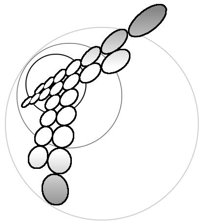
Fig.1. A Ring (1) rolling without slip on a surface of the rotating disk
(2). The axis (3) is already removed.
Fig.2. The coordinate system.
Fig.3 The reasons for rolling friction force arising: a) deformation; b) microobstacles, c) adhesion.
Fig.4. The regions of the constant stability type of the ball motion.
Fig.5 The path of the ball in the laboratory system of frame for: a) h = 0.005, v0 =0; b) h =0.002, v0 =0.004; c)h = 0.005, v0 =0.086.
Fig.6.The time dependence of the kinetic energy of the ball for a) h = 0 ; b) h = 0.005.
Fig.7.Ball motion on the turntable with a board.